
1:32nd scale Hanriot HD.1
+4
Jess
Xan
Nieuport
Mike
8 participants
Page 1 sur 2
Page 1 sur 2 • 1, 2 
1:32nd scale Hanriot HD.1
par Mike Dim 5 Nov - 11:02
Hi all,
Something I don't do is to build two models at the same time.
However I'm starting a double build.
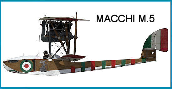
The first is the 'HPH Models' 1:32nd scale resin model of the Italian Macchi M.5 floatplane.
This is a commission build for the Commander of the Italian Frigate 'Federico Martinengo'.
His ship was named after the Italian naval pilot of WW1, Federico Carlo Martinengo.
I've previously built a version of this model and have a build log on my web site.
The only differences between the two models will be the aircraft markings.
As such, I won't create a build log for this model here on the forum.
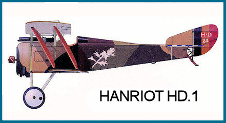
The second build is the 'Lukgraph' 1:32nd scale resin Hanriot HD.1.
This was on order before 'Copper State Models' announced their intention to release this model.
The model will be of the Belgian Hanriot HD.1, serial HD 24 of Willy Coppens, Escadrille 9me during 1918
Mike
Something I don't do is to build two models at the same time.
However I'm starting a double build.
The first is the 'HPH Models' 1:32nd scale resin model of the Italian Macchi M.5 floatplane.
This is a commission build for the Commander of the Italian Frigate 'Federico Martinengo'.
His ship was named after the Italian naval pilot of WW1, Federico Carlo Martinengo.
I've previously built a version of this model and have a build log on my web site.
The only differences between the two models will be the aircraft markings.
As such, I won't create a build log for this model here on the forum.
The second build is the 'Lukgraph' 1:32nd scale resin Hanriot HD.1.
This was on order before 'Copper State Models' announced their intention to release this model.
The model will be of the Belgian Hanriot HD.1, serial HD 24 of Willy Coppens, Escadrille 9me during 1918
Mike
Dernière édition par Mike le Dim 5 Nov - 12:35, édité 1 fois
Mike- Messages : 113
Date d'inscription : 18/07/2023
Age : 74
Localisation : Coningsby, UK -

Re: 1:32nd scale Hanriot HD.1
par Nieuport Dim 5 Nov - 12:14
Hello,
2 nice planes !!!
Best regards,
Eric
2 nice planes !!!
Best regards,
Eric

Nieuport- Messages : 398
Date d'inscription : 24/04/2018
Age : 57
Localisation : Poitiers
Re: 1:32nd scale Hanriot HD.1
par Xan Mer 8 Nov - 8:33
Waow! I can't wait to see how the new lukgraf is!

Xan- Admin
- Messages : 2664
Date d'inscription : 13/04/2018
Age : 57
Localisation : Euskal Herria -
Re: 1:32nd scale Hanriot HD.1
par Mike Mar 14 Nov - 17:21
Hi all,
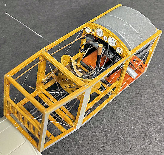
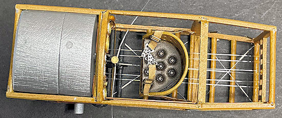
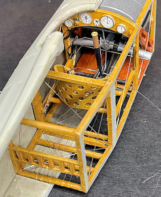
The cockpit has been completed and the fuselage closed up.
As usual, working on 3D printed complete assemblies, such cockpit frames and engines, can limit what can be achieved with painting and assembly.
However, this kit didn't present too many problems.
That said I did replace the kit supplied cockpit instrument decals and pilots seat straps.
I used appropriate instrument decals from the 'Airscale' WW1 generic instrument set.
Also the kit supplied photo-etch seat belts, which are basic to say the least, are too short.
They can't be attached to where they should be on the cockpit side frames and still reach over the pilots seat.
So they were replaced with 'HGW models' fabric belts made up from my 'spares'.
I've added the following:
Throtle control rods (0.4mm Nickel Silver tube).
Fuel level indicator (0.5 mm Brass tube and copper wire).
Pulsometer pipe ('MFH' 0.4mm flexible tube).
Tachometer drive cable ('MFH' 0.4mm flexible tube).
Unidentified pipe on cockpit left (copper wire).
Machine gun trigger cable (lead wire).
Rudder, aileron and elevator control cables (0.12 mm mono-filament and 0.4 mm Brass tube).
Cockpit side, bottom and seat frame crossed bracing wires (0.12 mm mono-filament and 0.4 mm Brass tube).
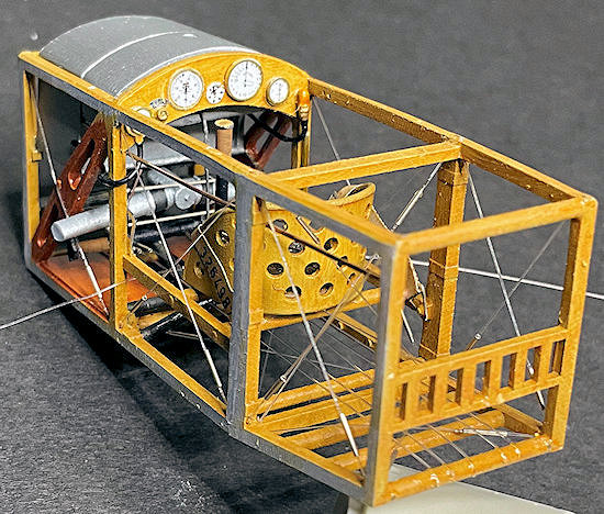
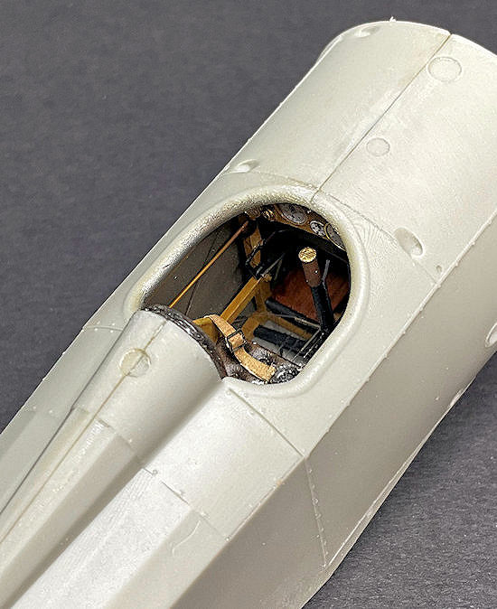
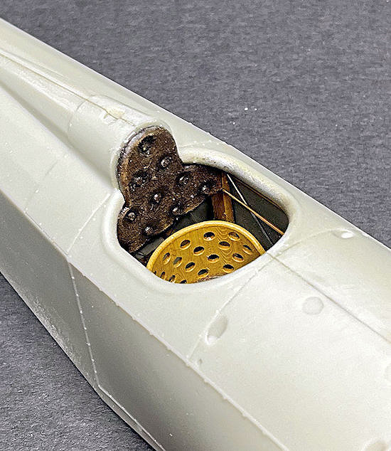
The cockpit opening of this aircraft is smaller than most, so even less is visible once the fuselage is closed up.
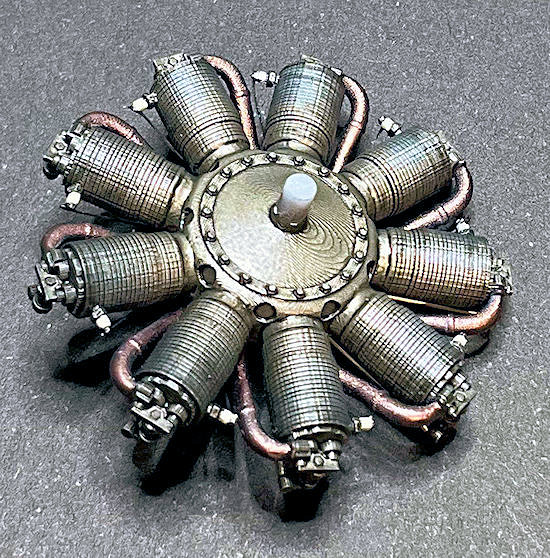
Also the engine is complete.
The only additions made were adding valve push rods (0.4mm Nickel-Silver tube).
Spark plug ignition leads ('EZ' black line).
Mike
The cockpit has been completed and the fuselage closed up.
As usual, working on 3D printed complete assemblies, such cockpit frames and engines, can limit what can be achieved with painting and assembly.
However, this kit didn't present too many problems.
That said I did replace the kit supplied cockpit instrument decals and pilots seat straps.
I used appropriate instrument decals from the 'Airscale' WW1 generic instrument set.
Also the kit supplied photo-etch seat belts, which are basic to say the least, are too short.
They can't be attached to where they should be on the cockpit side frames and still reach over the pilots seat.
So they were replaced with 'HGW models' fabric belts made up from my 'spares'.
I've added the following:
Throtle control rods (0.4mm Nickel Silver tube).
Fuel level indicator (0.5 mm Brass tube and copper wire).
Pulsometer pipe ('MFH' 0.4mm flexible tube).
Tachometer drive cable ('MFH' 0.4mm flexible tube).
Unidentified pipe on cockpit left (copper wire).
Machine gun trigger cable (lead wire).
Rudder, aileron and elevator control cables (0.12 mm mono-filament and 0.4 mm Brass tube).
Cockpit side, bottom and seat frame crossed bracing wires (0.12 mm mono-filament and 0.4 mm Brass tube).
The cockpit opening of this aircraft is smaller than most, so even less is visible once the fuselage is closed up.
Also the engine is complete.
The only additions made were adding valve push rods (0.4mm Nickel-Silver tube).
Spark plug ignition leads ('EZ' black line).
Mike
Mike- Messages : 113
Date d'inscription : 18/07/2023
Age : 74
Localisation : Coningsby, UK -
CRICKEY aime ce message
Xan- Admin
- Messages : 2664
Date d'inscription : 13/04/2018
Age : 57
Localisation : Euskal Herria -
Jess- Messages : 674
Date d'inscription : 29/03/2023
Age : 53
Localisation : Alsace
Re: 1:32nd scale Hanriot HD.1
par Mike Mer 15 Nov - 19:07
Hi all,
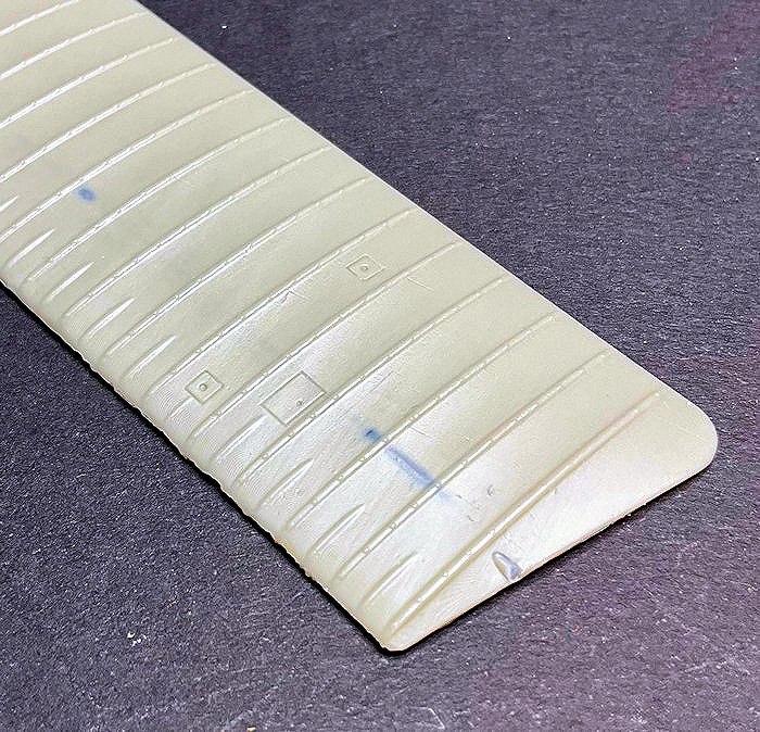
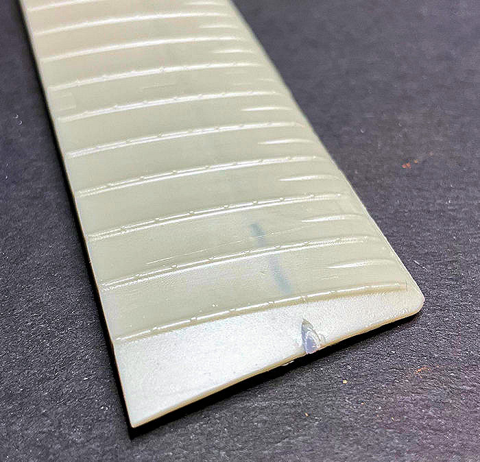
All of the flight surfaces of the kit parts (wings, tail plane, elevator, ailerons, fin and rudder) have heavy and pronounced ribs, which will need sanding down.
These rib tapes caused rippling along the wing leading edges, which also needs to be removed.
Lastly, the internal metal reinforcing rods do keep the resin wings from distorting.
However they are very close to the surface and the ends have broken through the wing tips.
So filling and sanding required,
Mike
Mike- Messages : 113
Date d'inscription : 18/07/2023
Age : 74
Localisation : Coningsby, UK -
Re: 1:32nd scale Hanriot HD.1
par Mike Ven 17 Nov - 12:59
Hi all,
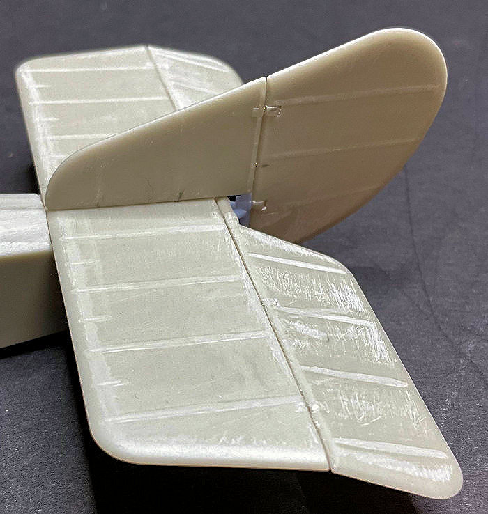
Well I'll start with the flight surfaces.
I've sanded down all of the over scale rib tapes on all of the flight surfaces.
I've also filled then sanded where the wing internal support rods protruded from the wing tips.
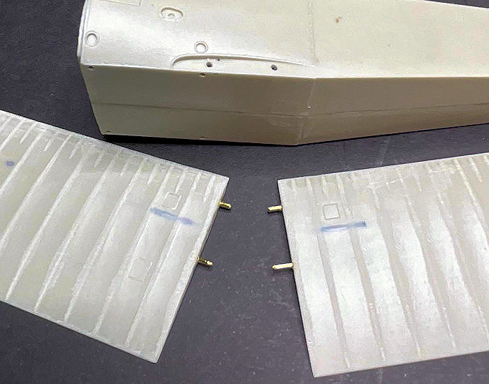
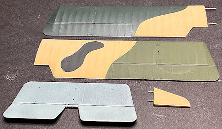
The tail plane locating recess on the rear of the fuselage has two huge 1.2 mm diameter holes.
I assume these were intended to be used to locate the tail plane onto the fuselage.
However, the underside of the resin tail plane has no locating stubs and is smooth.
To ensure the tail plane located correctly, I resorted to inserting 1.2 mm diameter tubes into the fuselage holes, with 0.5 mm diameter rods fitted in the tubes.
I drilled the locating holes through the tail plane and fitted it down onto the rods.
The fin is just a butt join to the top of the tail plane - not good.
So I drilled two 0.5 mm diameter holes in the base of the fin, so it could be located onto the protruding rods.
The rudder is also a butt join the the rear of the fin, so these were drilled and rods inserted to support the rudder.
I did the same to attach the elevator to the tail plane, which enabled me to angle the elevator down slightly.
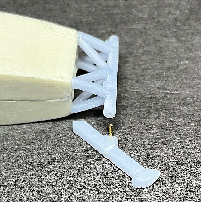
The 3D printed tail skid support and the tail skid are again just butt joins.
Therefore, I drilled and pinned the tail skid to the bottom of the rudder post on the support frame.
This should provide a sturdier joint for the tail skid.
Also I has to sand down the over-scale thickness of the tail skid to a more 'in-scale' thickness.
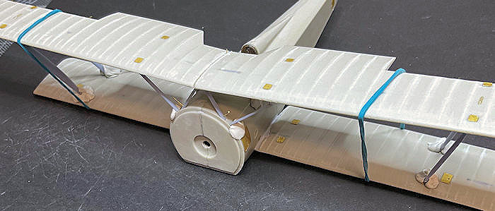
The lower wing halves are intended to have rods fitted to support them in the fuselage.
Whilst the wing roots can be drilled far enough to add sufficient rods, the amount of fuselage support is minimal.
Drilling to far into the fuselage means you'll hit the cockpit internal structure or components.
The wing rods are good enough to locate the wings into the fuselage.
But I think most of the wing support will be from the adhesive joints between the wing roots and fuselage.
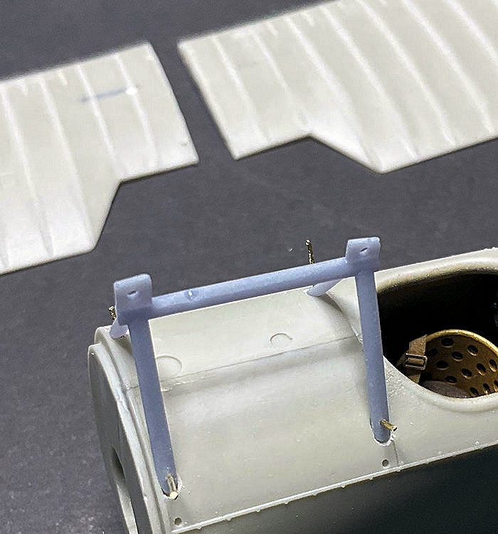
The upper wing halves are intended to be joined together using inserted rods, which pass through holes in the top of the 3D printed cabane struts assembly.
However, the spread of the printed cabane struts is too wide to fit into the fuselage recesses.
Pressure needs to be applied to get the struts located and given how brittle the printed resin is, they could break under pressure.
Also the ends of the struts are not shaped to fit into their locating recesses in the fuselage.
I reshaped the strut ends and managed to drill and pin the struts onto the fuselage to hold them in position.
So now it's onto sorting out the upper wing installation.
Pretty good for the kit only cost 145 GBP ???
Mike
Traduction google (ajout de Xan):
Salut tout le monde,
Eh bien, je vais commencer par les surfaces de vol.
J'ai poncé toutes les bandes côtelées surdimensionnées sur toutes les surfaces de vol.
J'ai également rempli puis poncé l'endroit où les tiges de support internes de l'aile dépassaient des extrémités des ailes.
L'évidement de localisation de l'empennage à l'arrière du fuselage comporte deux énormes trous de 1,2 mm de diamètre.
Je suppose qu'ils étaient destinés à être utilisés pour localiser l'empennage sur le fuselage.
Cependant, le dessous de l'empennage en résine n'a pas de plots de localisation et est lisse.
Pour m'assurer que l'empennage est correctement positionné, j'ai eu recours à l'insertion de tubes de 1,2 mm de diamètre dans les trous du fuselage, avec des tiges de 0,5 mm de diamètre insérées dans les tubes.
J'ai percé les trous de positionnement à travers l'empennage et je les ai installés sur les tiges.
L'aileron n'est qu'un joint abouté au sommet de l'empennage - ce n'est pas bon.
J'ai donc percé deux trous de 0,5 mm de diamètre à la base de l'aileron, afin de pouvoir le situer sur les tiges saillantes.
Le gouvernail est également un bout qui rejoint l'arrière de l'aileron, c'est pourquoi ceux-ci ont été percés et des tiges insérées pour soutenir le gouvernail.
J'ai fait de même pour fixer la gouverne de profondeur à l'empennage, ce qui m'a permis d'incliner légèrement la gouverne de profondeur vers le bas.
Le support du patin arrière imprimé en 3D et le patin arrière ne sont encore une fois que des joints bout à bout.
Par conséquent, j’ai percé et épinglé le patin de queue au bas du poteau du gouvernail sur le cadre de support.
Cela devrait fournir une articulation plus solide pour le patin arrière.
Je dois également poncer l'épaisseur surdimensionnée du patin arrière pour obtenir une épaisseur plus « à l'échelle ».
Les moitiés inférieures de l'aile sont destinées à être dotées de tiges pour les soutenir dans le fuselage.
Bien que les racines des ailes puissent être percées suffisamment loin pour ajouter suffisamment de tiges, la quantité de support du fuselage est minime.
Percer trop loin dans le fuselage signifie que vous toucherez la structure interne ou les composants du cockpit.
Les tiges d'aile sont suffisamment bonnes pour localiser les ailes dans le fuselage.
Mais je pense que la majeure partie du support de l'aile proviendra des joints adhésifs entre les emplantures de l'aile et le fuselage.
Les moitiés supérieures de l'aile sont destinées à être assemblées à l'aide de tiges insérées, qui passent à travers des trous situés dans la partie supérieure de l'assemblage des entretoises de cabane imprimées en 3D.
Cependant, l'étendue des entretoises de cabane imprimées est trop large pour s'insérer dans les évidements du fuselage.
Une pression doit être appliquée pour localiser les entretoises et, étant donné la fragilité de la résine imprimée, elles pourraient se briser sous la pression.
De plus, les extrémités des entretoises ne sont pas conçues pour s'insérer dans leurs évidements de positionnement dans le fuselage.
J'ai remodelé les extrémités des jambes de force et j'ai réussi à percer et épingler les jambes de force sur le fuselage pour les maintenir en position.
Il s'agit maintenant de régler l'installation de l'aile supérieure.
Plutôt bien pour le kit qui ne coûte que 145 GBP ???
Mike
Well I'll start with the flight surfaces.
I've sanded down all of the over scale rib tapes on all of the flight surfaces.
I've also filled then sanded where the wing internal support rods protruded from the wing tips.
The tail plane locating recess on the rear of the fuselage has two huge 1.2 mm diameter holes.
I assume these were intended to be used to locate the tail plane onto the fuselage.
However, the underside of the resin tail plane has no locating stubs and is smooth.
To ensure the tail plane located correctly, I resorted to inserting 1.2 mm diameter tubes into the fuselage holes, with 0.5 mm diameter rods fitted in the tubes.
I drilled the locating holes through the tail plane and fitted it down onto the rods.
The fin is just a butt join to the top of the tail plane - not good.
So I drilled two 0.5 mm diameter holes in the base of the fin, so it could be located onto the protruding rods.
The rudder is also a butt join the the rear of the fin, so these were drilled and rods inserted to support the rudder.
I did the same to attach the elevator to the tail plane, which enabled me to angle the elevator down slightly.
The 3D printed tail skid support and the tail skid are again just butt joins.
Therefore, I drilled and pinned the tail skid to the bottom of the rudder post on the support frame.
This should provide a sturdier joint for the tail skid.
Also I has to sand down the over-scale thickness of the tail skid to a more 'in-scale' thickness.
The lower wing halves are intended to have rods fitted to support them in the fuselage.
Whilst the wing roots can be drilled far enough to add sufficient rods, the amount of fuselage support is minimal.
Drilling to far into the fuselage means you'll hit the cockpit internal structure or components.
The wing rods are good enough to locate the wings into the fuselage.
But I think most of the wing support will be from the adhesive joints between the wing roots and fuselage.
The upper wing halves are intended to be joined together using inserted rods, which pass through holes in the top of the 3D printed cabane struts assembly.
However, the spread of the printed cabane struts is too wide to fit into the fuselage recesses.
Pressure needs to be applied to get the struts located and given how brittle the printed resin is, they could break under pressure.
Also the ends of the struts are not shaped to fit into their locating recesses in the fuselage.
I reshaped the strut ends and managed to drill and pin the struts onto the fuselage to hold them in position.
So now it's onto sorting out the upper wing installation.
Pretty good for the kit only cost 145 GBP ???
Mike
Traduction google (ajout de Xan):
Salut tout le monde,
Eh bien, je vais commencer par les surfaces de vol.
J'ai poncé toutes les bandes côtelées surdimensionnées sur toutes les surfaces de vol.
J'ai également rempli puis poncé l'endroit où les tiges de support internes de l'aile dépassaient des extrémités des ailes.
L'évidement de localisation de l'empennage à l'arrière du fuselage comporte deux énormes trous de 1,2 mm de diamètre.
Je suppose qu'ils étaient destinés à être utilisés pour localiser l'empennage sur le fuselage.
Cependant, le dessous de l'empennage en résine n'a pas de plots de localisation et est lisse.
Pour m'assurer que l'empennage est correctement positionné, j'ai eu recours à l'insertion de tubes de 1,2 mm de diamètre dans les trous du fuselage, avec des tiges de 0,5 mm de diamètre insérées dans les tubes.
J'ai percé les trous de positionnement à travers l'empennage et je les ai installés sur les tiges.
L'aileron n'est qu'un joint abouté au sommet de l'empennage - ce n'est pas bon.
J'ai donc percé deux trous de 0,5 mm de diamètre à la base de l'aileron, afin de pouvoir le situer sur les tiges saillantes.
Le gouvernail est également un bout qui rejoint l'arrière de l'aileron, c'est pourquoi ceux-ci ont été percés et des tiges insérées pour soutenir le gouvernail.
J'ai fait de même pour fixer la gouverne de profondeur à l'empennage, ce qui m'a permis d'incliner légèrement la gouverne de profondeur vers le bas.
Le support du patin arrière imprimé en 3D et le patin arrière ne sont encore une fois que des joints bout à bout.
Par conséquent, j’ai percé et épinglé le patin de queue au bas du poteau du gouvernail sur le cadre de support.
Cela devrait fournir une articulation plus solide pour le patin arrière.
Je dois également poncer l'épaisseur surdimensionnée du patin arrière pour obtenir une épaisseur plus « à l'échelle ».
Les moitiés inférieures de l'aile sont destinées à être dotées de tiges pour les soutenir dans le fuselage.
Bien que les racines des ailes puissent être percées suffisamment loin pour ajouter suffisamment de tiges, la quantité de support du fuselage est minime.
Percer trop loin dans le fuselage signifie que vous toucherez la structure interne ou les composants du cockpit.
Les tiges d'aile sont suffisamment bonnes pour localiser les ailes dans le fuselage.
Mais je pense que la majeure partie du support de l'aile proviendra des joints adhésifs entre les emplantures de l'aile et le fuselage.
Les moitiés supérieures de l'aile sont destinées à être assemblées à l'aide de tiges insérées, qui passent à travers des trous situés dans la partie supérieure de l'assemblage des entretoises de cabane imprimées en 3D.
Cependant, l'étendue des entretoises de cabane imprimées est trop large pour s'insérer dans les évidements du fuselage.
Une pression doit être appliquée pour localiser les entretoises et, étant donné la fragilité de la résine imprimée, elles pourraient se briser sous la pression.
De plus, les extrémités des entretoises ne sont pas conçues pour s'insérer dans leurs évidements de positionnement dans le fuselage.
J'ai remodelé les extrémités des jambes de force et j'ai réussi à percer et épingler les jambes de force sur le fuselage pour les maintenir en position.
Il s'agit maintenant de régler l'installation de l'aile supérieure.
Plutôt bien pour le kit qui ne coûte que 145 GBP ???
Mike
Mike- Messages : 113
Date d'inscription : 18/07/2023
Age : 74
Localisation : Coningsby, UK -
CRICKEY aime ce message
Re: 1:32nd scale Hanriot HD.1
par Mike Ven 17 Nov - 17:07
Hi all,
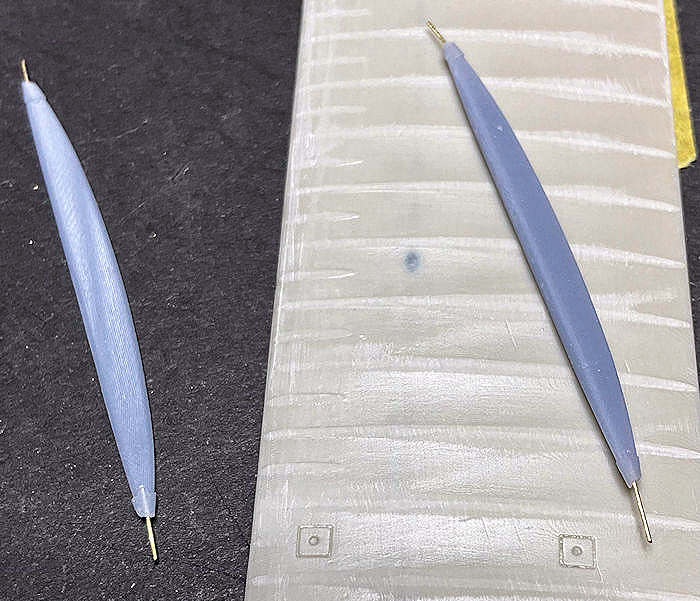
Again, a problem to overcome.
The interplane struts are 3D printed so have no internal support rods.
Also, they have no end locators.
However, the upper and lower wings have locating recesses.
I assume the original intention was that rods, from presumably resin struts, would use these locating recesses.
So I drilled 0.3 mm diameter holes into the end of the struts and added Brass locating rods.
These will hopefully provide better location for the 3D printed interplane struts.
That is assuming that the brittle resin struts don't break during assembly or under the weight of the solid resin upper wing halves - we'll see,
Mike
Mike- Messages : 113
Date d'inscription : 18/07/2023
Age : 74
Localisation : Coningsby, UK -
Re: 1:32nd scale Hanriot HD.1
par Veneto Vittorio Ven 17 Nov - 23:12
Hi Mike,
Nice progress. Setting up is always a bit long.
The Hanriot HD. 1 is really a beautiful plane (even more in Italian markings).
Nice progress. Setting up is always a bit long.
The Hanriot HD. 1 is really a beautiful plane (even more in Italian markings).
Veneto Vittorio- Messages : 133
Date d'inscription : 27/09/2022
Age : 58
Localisation : Gallia Narbonensis

JP- Messages : 3619
Date d'inscription : 13/05/2018
Age : 62
Localisation : Ambutrix
Re: 1:32nd scale Hanriot HD.1
par Mike Ven 24 Nov - 12:05
Hi all,
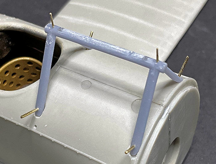
The upper wing had a dihedral angle of 3 degrees, the lower wing was horizontal.
Test fitting the upper wing revealed that the cabane side support struts were too short.
The interplane struts fitted correctly.
Therefore I removed the two rod support lugs on the 3D printed cabane strut assembly.
I then drilled and inserted 0.4 mm diameter rod into the top bar to give the required wing half separation.
This allowed the upper wing to be slightly lower and rest on the cabane top bar.
The upper wing test fit after this was correct,
Mike
Mike- Messages : 113
Date d'inscription : 18/07/2023
Age : 74
Localisation : Coningsby, UK -
Re: 1:32nd scale Hanriot HD.1
par Mike Ven 24 Nov - 21:56
Hi all,
The decal sheet supplied in the kit covers all of the schemes.
However, the individual decals are printed as part of the entire carrier film on the sheet.
As such carrier film will probably show around the applied decal.
Therefore, each decal will probably have to be cut out as close as possible to the edges of the decal, before applying to the model.
Also, some of the decals seem to be slightly semi-translucent, meaning the painted colours underneath will show through the decals once applied.
This is not good for a kit of this price, especially considering different painted colour schemes and the intricate shapes of the various decals.
'Cartograph' decals these are certainly not.
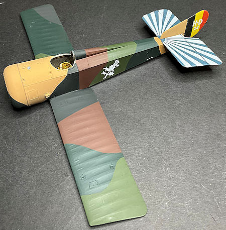
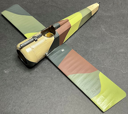
Anyway, the basic French five colour camouflage scheme has been applied.
'Tamiya' acrylics used were:
Beige - Desert Yellow (XF59)
Light Green - Olive Green (XF58)
Dark Green - Dark Green 2 (XF70)/NATO Black (XF69)
Chestnut Brown - Flat Brown (XF10)
Black - NATO Black (XF69)
Undersides 'Alclad' Duraluminium (ALC102) oversprayed with 'Tamiya' Light Blue (XF23).
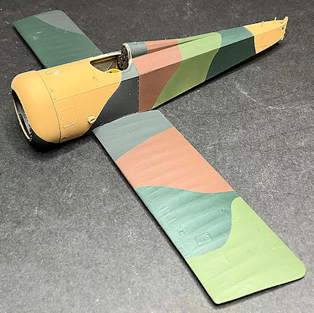
Mike
The decal sheet supplied in the kit covers all of the schemes.
However, the individual decals are printed as part of the entire carrier film on the sheet.
As such carrier film will probably show around the applied decal.
Therefore, each decal will probably have to be cut out as close as possible to the edges of the decal, before applying to the model.
Also, some of the decals seem to be slightly semi-translucent, meaning the painted colours underneath will show through the decals once applied.
This is not good for a kit of this price, especially considering different painted colour schemes and the intricate shapes of the various decals.
'Cartograph' decals these are certainly not.
Anyway, the basic French five colour camouflage scheme has been applied.
'Tamiya' acrylics used were:
Beige - Desert Yellow (XF59)
Light Green - Olive Green (XF58)
Dark Green - Dark Green 2 (XF70)/NATO Black (XF69)
Chestnut Brown - Flat Brown (XF10)
Black - NATO Black (XF69)
Undersides 'Alclad' Duraluminium (ALC102) oversprayed with 'Tamiya' Light Blue (XF23).
Mike
Mike- Messages : 113
Date d'inscription : 18/07/2023
Age : 74
Localisation : Coningsby, UK -
CRICKEY aime ce message
Re: 1:32nd scale Hanriot HD.1
par Xan Dim 26 Nov - 8:42
Hi mike,
A very serious have been done by Marc Chassard about those dope...
https://forum.ww1aircraftmodels.com/index.php?topic=7858.0
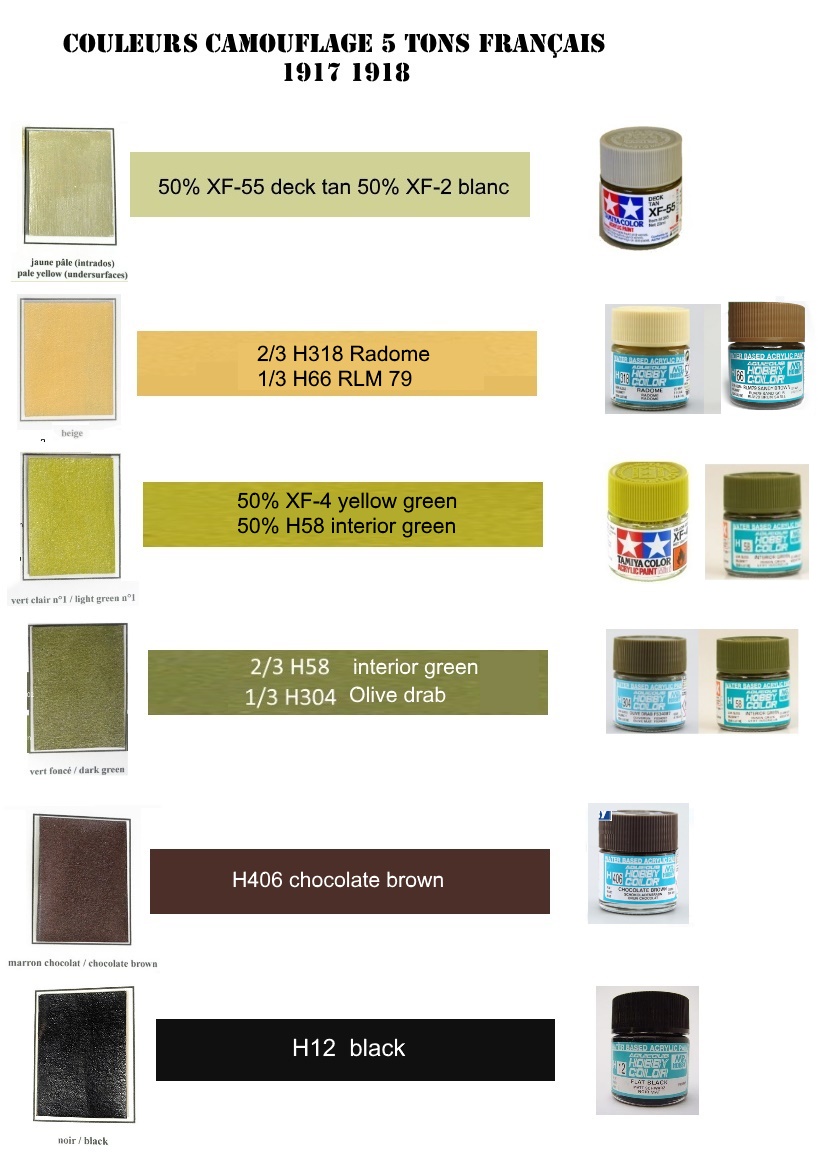
we did a sprecific topic there, I don't know if you saw it:
https://1914.forumactif.com/t231-camouflage-5-tons-francais-1918
Here the result of those investigation in this Morane:

A very serious have been done by Marc Chassard about those dope...
https://forum.ww1aircraftmodels.com/index.php?topic=7858.0
we did a sprecific topic there, I don't know if you saw it:
https://1914.forumactif.com/t231-camouflage-5-tons-francais-1918
Here the result of those investigation in this Morane:

Dernière édition par Xan le Dim 26 Nov - 8:51, édité 1 fois
Xan- Admin
- Messages : 2664
Date d'inscription : 13/04/2018
Age : 57
Localisation : Euskal Herria -
Re: 1:32nd scale Hanriot HD.1
par Xan Dim 26 Nov - 8:44
Your brown is too light in my opinion and the dark green "very green', I imagine it more olive drab.
But of course no one can be affirmative...
But of course no one can be affirmative...
Xan- Admin
- Messages : 2664
Date d'inscription : 13/04/2018
Age : 57
Localisation : Euskal Herria -
Re: 1:32nd scale Hanriot HD.1
par Mike Dim 26 Nov - 12:40
Hi Xan,
Thanks for this information.
I'll keep copies for future reference.
The photograph on my model does not show the actual colours correctly.
The Brown, black and beige are good.
However my green colours - I used the dark shade as my light green and my dark green is too dark.
To late to correct those now as I've applied the decals.
Lesson learnt,
Mike
Mike- Messages : 113
Date d'inscription : 18/07/2023
Age : 74
Localisation : Coningsby, UK -
Re: 1:32nd scale Hanriot HD.1
par Mike Dim 26 Nov - 16:34
Hi all,
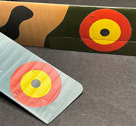
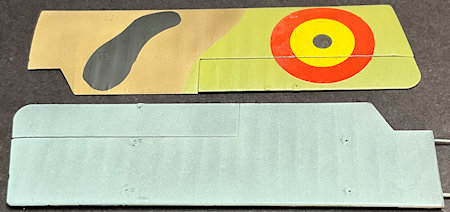
I've applied the required decals for this particular aircraft.
I found that as long as the decals are applied over a single colour, they do cover the painted surface under the decals.
However, the lighter coloured decals, especially the white colour, do show the painted surface through the decal.
This is more evident where light coloured decals are applied over contrasting coloured paints.
I've airbrushed a clear coat over the decals to seal and protect them during handling.
They will be airbrushed again later in the build during the weathering phase.
As the camouflage scheme is French, I painted the top of the tailplane and elevator with a base coat of 'Tamiya' Medium Blue (XF18).
The engine and engine cowl have also been fitted.
I found that the engine propeller shaft is not long enough to clear the engine cowl to locate the propeller.
So that's another problem to be sorted out,
Mike
Mike- Messages : 113
Date d'inscription : 18/07/2023
Age : 74
Localisation : Coningsby, UK -
CRICKEY aime ce message
Xan- Admin
- Messages : 2664
Date d'inscription : 13/04/2018
Age : 57
Localisation : Euskal Herria -
Re: 1:32nd scale Hanriot HD.1
par Mike Dim 26 Nov - 19:53
Hi all,
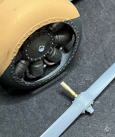
The propeller shaft on the engine is too short to allow the propeller to be fitted and be clear of the front of the engine cowl.
Therefore, I cat away the propeller shaft from the engine.
Using as a guide, the mark left from the shaft, I gradually drilled into the engine up to a size of 1.4 mm diameter.
A length of 1.4 mm diameter Brass tube was cut and secured into the propeller locating hole, using CA adhesive.
This allows the propeller shaft to be fitted into the engine with the propeller clear of the engine cowl,
Mike
Mike- Messages : 113
Date d'inscription : 18/07/2023
Age : 74
Localisation : Coningsby, UK -
Re: 1:32nd scale Hanriot HD.1
par Mike Jeu 30 Nov - 14:12
Hi all,
I've replaced three of the colours as I wasn't satisfied - thanks Xan
Light Green - ‘Hataka’ C093 Green (FS34258)
Dark Green - ‘Hataka’ C301 Dark Olive Green (FS34096)
Beige - ‘Hataka’ C060 USMC Sand
These have yet to be weathered so will dull down slightly.
I've fitted the single, central machine gun, using a modified 'Gaspatch' 'Vickers' 11mm 'Balloon Buster', as used by Willy Coppens.
This was p[ainted with 'Alclad' Gunmetal (ALC-120) then dry brushed with 'Mr. Colour' Super Iron 2 (SM203).
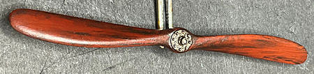
The propeller was base coated with 'Tamiya' Flat Red (XF7) and Full Red (XF19) mixed 70/30% ratio.
Windsor & Newton’ Griffin (Alkyd) Vandyke Brown oil paint was then applied to represent the wood effect.
The hub plates were brush painted with ‘Mr. Colour’ Stainless Steel (213) the ’AK Interactive’ Kerosene wash (AK2039).
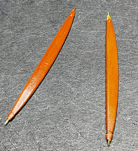
The interplane struts were base coated with 'Tamiya' Desert Yellow (XF59).
Windsor & Newton’ Griffin (Alkyd) Burnt Sienna oil paint was then applied to represent the wood effect.
Whilst test fitting the tail skid, it snapped in half - no surprise given the brittleness of the 3D printed parts.
So that now needs to be addressed,
Mike
I've replaced three of the colours as I wasn't satisfied - thanks Xan
Light Green - ‘Hataka’ C093 Green (FS34258)
Dark Green - ‘Hataka’ C301 Dark Olive Green (FS34096)
Beige - ‘Hataka’ C060 USMC Sand
These have yet to be weathered so will dull down slightly.
I've fitted the single, central machine gun, using a modified 'Gaspatch' 'Vickers' 11mm 'Balloon Buster', as used by Willy Coppens.
This was p[ainted with 'Alclad' Gunmetal (ALC-120) then dry brushed with 'Mr. Colour' Super Iron 2 (SM203).
The propeller was base coated with 'Tamiya' Flat Red (XF7) and Full Red (XF19) mixed 70/30% ratio.
Windsor & Newton’ Griffin (Alkyd) Vandyke Brown oil paint was then applied to represent the wood effect.
The hub plates were brush painted with ‘Mr. Colour’ Stainless Steel (213) the ’AK Interactive’ Kerosene wash (AK2039).
The interplane struts were base coated with 'Tamiya' Desert Yellow (XF59).
Windsor & Newton’ Griffin (Alkyd) Burnt Sienna oil paint was then applied to represent the wood effect.
Whilst test fitting the tail skid, it snapped in half - no surprise given the brittleness of the 3D printed parts.
So that now needs to be addressed,
Mike
Mike- Messages : 113
Date d'inscription : 18/07/2023
Age : 74
Localisation : Coningsby, UK -
CRICKEY aime ce message
JP- Messages : 3619
Date d'inscription : 13/05/2018
Age : 62
Localisation : Ambutrix

CRICKEY- Messages : 419
Date d'inscription : 02/02/2022
Age : 55
Localisation : Essone
Re: 1:32nd scale Hanriot HD.1
par Mike Ven 1 Déc - 23:20
Hi all,
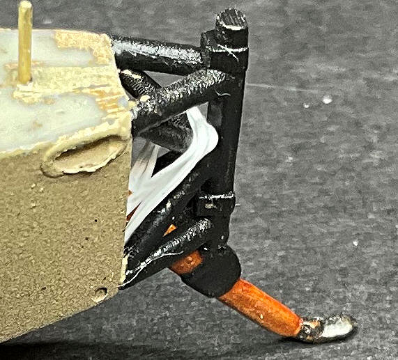
As I said previously, the 3D printed tail skid snapped in half while I was test fitting it
Rather than trying to repair and use the tail skid, I decided to scratch a replacement.
This was made using 1.4 mm diameter Brass tube and 0.5 mm diameter rod.
The tube was flattened to an airfoil profile and reinforced internally with the rod.
the kit supplied tail skid support frame has the bottom of the rudder post.
This is too long as the tail skid was attached at the bottom of the support frame.
Therefore the rudder post was shortened and a hole of 0.5 mm diameter was drilled up into the post.
This hole was used to locate the support Brass rod on the tail skid.
Once secured to the support frame, the 'bungee' type suspension cords were added, using 'EZ' White (heavy) stretch line.
Mike
Mike- Messages : 113
Date d'inscription : 18/07/2023
Age : 74
Localisation : Coningsby, UK -
Nieuport aime ce message
Re: 1:32nd scale Hanriot HD.1
par Xan Dim 3 Déc - 8:21
Joli bricolage, la béquille etait en soi fragile et aurait cassé tôt ou tard.... Maintenant, tout est maintenant solide, bravo!
Xan- Admin
- Messages : 2664
Date d'inscription : 13/04/2018
Age : 57
Localisation : Euskal Herria -
Re: 1:32nd scale Hanriot HD.1
par Jess Dim 3 Déc - 9:04
indeed. It is virtually impossible to distinguish from your original print and you have certainly gained in solidity. Nice job.
Jess- Messages : 674
Date d'inscription : 29/03/2023
Age : 53
Localisation : Alsace
Page 1 sur 2 • 1, 2
» 1:32nd scale Hansa-Brandenburg W.12
» 1:32nd scale Bristol F.2b
» 1:32nd scale Macchi M.5
» 1:32nd scale Halberstadt D.II
» Bristol F.2b
» 1:32nd scale Bristol F.2b
» 1:32nd scale Macchi M.5
» 1:32nd scale Halberstadt D.II
» Bristol F.2b
Page 1 sur 2
Permission de ce forum:
Vous ne pouvez pas répondre aux sujets dans ce forum|
|
|